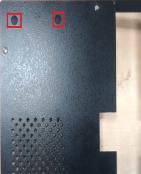
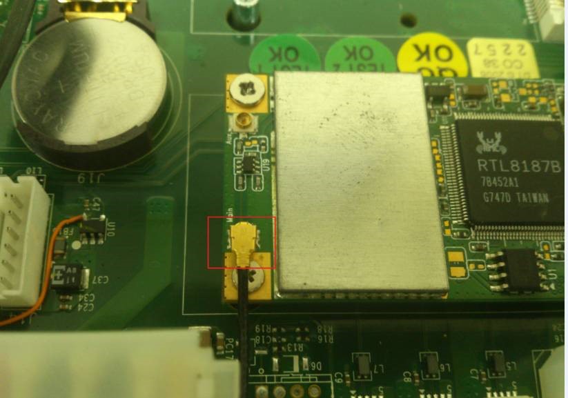
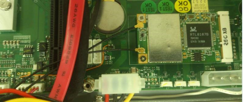
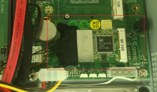
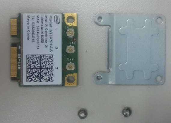
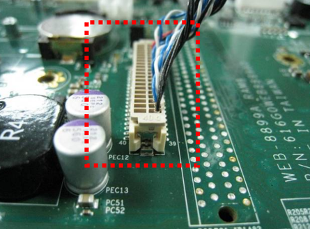
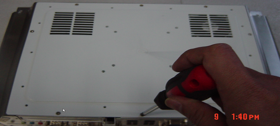
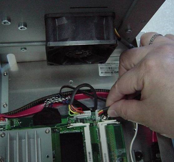
1.Remove all Rubber plug and screws on rear housing.
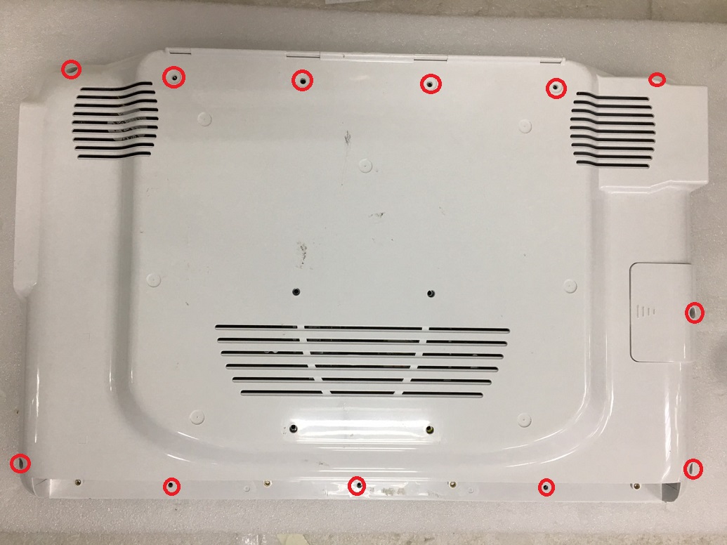
proimages/FAQ/How_to_remove_back_cover_and_clear_CMOS-WMP-22H/How_to_remove_back_cover_and_clear_CMOS_-_WMP-22H(back_cover.jpg

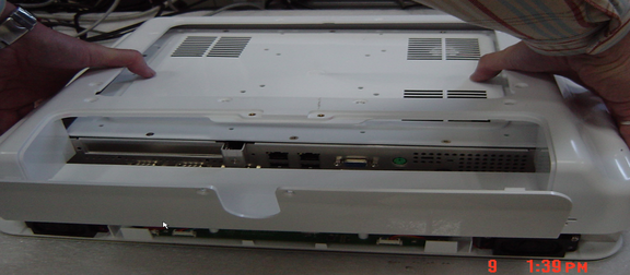
2.Remove the HDD cover and rear housing.
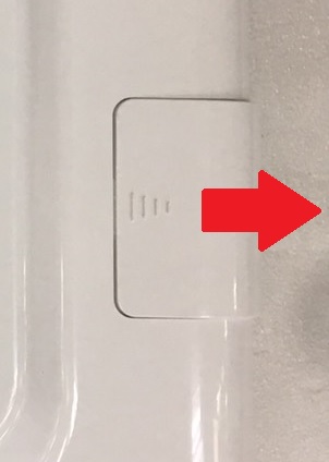
proimages/FAQ/How_to_remove_back_cover_and_clear_CMOS-WMP-22H/How_to_remove_back_cover_and_clear_CMOS_-_WMP-22H(remove_HDD_cover.jpg

3.Remove all the screws on the bracket, then open the bracket.
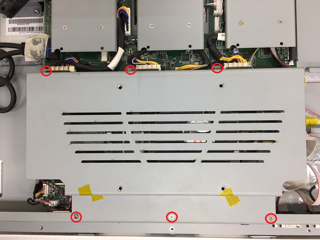
proimages/FAQ/How_to_remove_back_cover_and_clear_CMOS-WMP-22H/How_to_remove_back_cover_and_clear_CMOS_-_WMP-22H(bracket_1.jpg

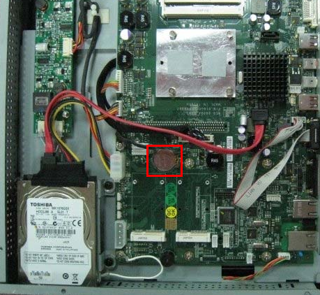
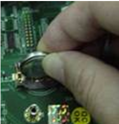
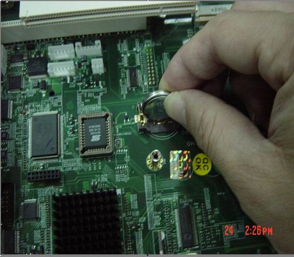
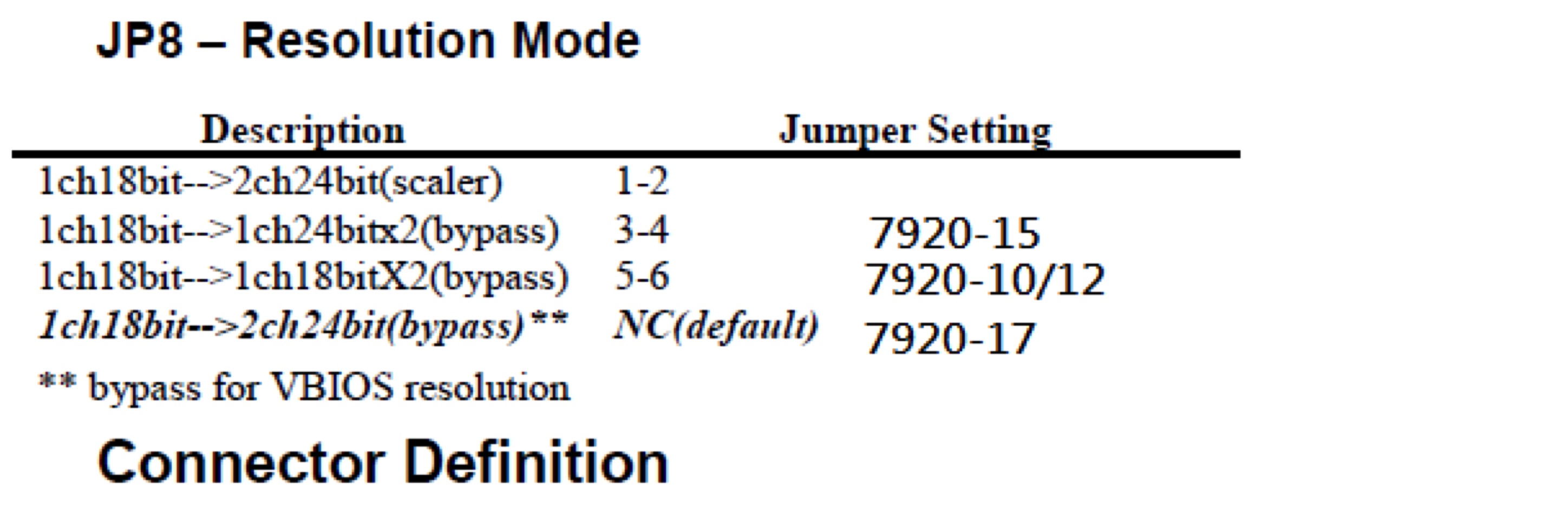
4.Short the two pins of the coin battery, and set the JP5 to 2-3(default is 1-2).proimages/FAQ/How_to_remove_back_cover_and_clear_CMOS-WMP-22H/How_to_remove_back_cover_and_clear_CMOS_-_WMP-22H(clear_CMOS.jpg
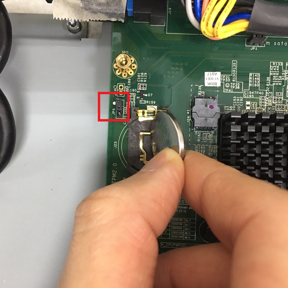
5.Set the JP5 to 1-2, and install the coin battery, bracket, the rear housing, and the HDD cover.
1.Remove all Rubber plug and screws on rear housing.
proimages/FAQ/How_to_remove_rear_cover_and_install_PCI-E_card-WMP-22G/How_to_remove_rear_cover_and_install_PCI-E_card_For_WMP-22G(back_cover).jpg

2.Remove HDD cover & rear cover
proimages/FAQ/How_to_remove_rear_cover_and_install_PCI-E_card-WMP-22G/How_to_remove_rear_cover_and_install_PCI-E_card_For_WMP-22G(remove_HDD_cover).jpg proimages/FAQ/How_to_remove_rear_cover_and_install_PCI-E_card-WMP-22G/How_to_remove_rear_cover_and_install_PCI-E_card_For_WMP-22G(remove_back_cover).jpg

3.Remove PCI bracket and install card.
proimages/FAQ/How_to_remove_rear_cover_and_install_PCI-E_card-WMP-22G/How_to_remove_rear_cover_and_install_PCI-E_card_For_WMP-22G(remove_pcie_bracket).jpgproimages/FAQ/How_to_remove_rear_cover_and_install_PCI-E_card-WMP-22G/How_to_remove_rear_cover_and_install_PCI-E_card_For_WMP-22G(install_card).jpg

4.Done.

1.Release screws on rear cover as below:
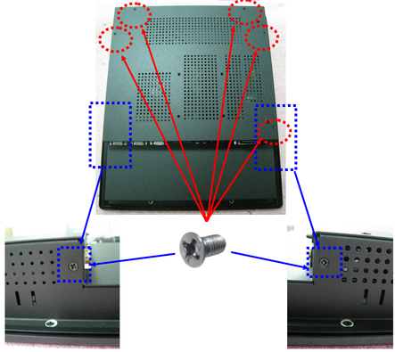
proimages/FAQ/How_to_remove_rear_cover_and_check_SATA_cable_connection.1.png

proimages/FAQ/How_to_remove_rear_cover_and_check_SATA_cable_connection.1-2.png

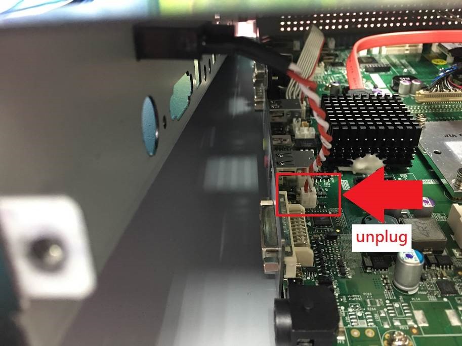
2 Remove rear cover and disconnect power switch cable.
proimages/FAQ/How_to_remove_rear_cover_and_check_SATA_cable_connection.2-1.jpg
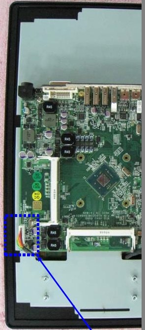
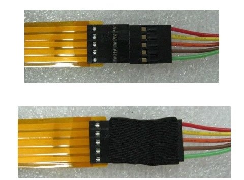
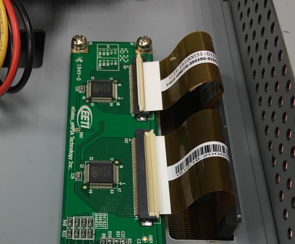
3 Check the cable connection of touch, and check whether there has any damage on the cable. 
proimages/FAQ/How_to_remove_the_rear_cover_and_check_touch_cable_connection.3-1.jpgproimages/FAQ/How_to_remove_the_rear_cover_and_check_touch_cable_connection.3-2.jpg
4. Done. 
1.Release screws on rear cover as below:
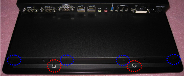
proimages/FAQ/How_to_remove_rear_cover_and_check_SATA_cable_connection.1.png

proimages/FAQ/How_to_remove_rear_cover_and_check_SATA_cable_connection.1-2.png

2 Remove rear cover and disconnect power switch cable.
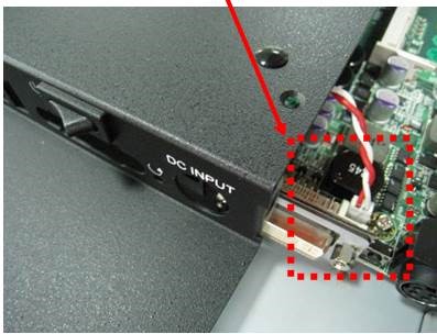
proimages/FAQ/How_to_remove_rear_cover_and_check_SATA_cable_connection.2-1.jpg
3 Check cable connection of SATA and power 
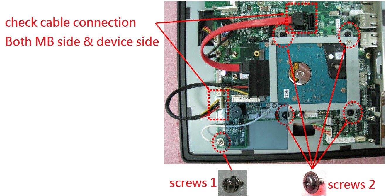
proimages/FAQ/How_to_remove_rear_cover_and_check_SATA_cable_connection.3.jpg
4. Done. 
1.When system power on(Connect USB CD-ROM) , press del key into BIOS setup screen .
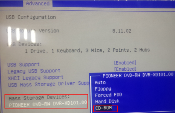
2.Select Advanced > USB configuration > Change CD-ROM setting from AUTO to CD-ROM
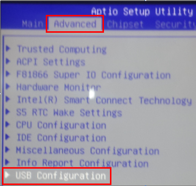
proimages/FAQ/How_to_install_Debain_8.1_on_WEB-A8A0A8A1.2-1.png proimages/FAQ/How_to_install_Debain_8.1_on_WEB-A8A0A8A1.2-2.png

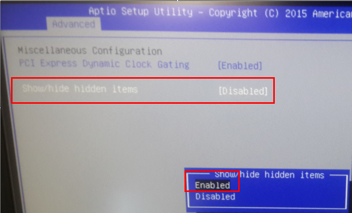
3.Select Advanced > Miscellaneous Config… > Show/Hide hidden items > Enable
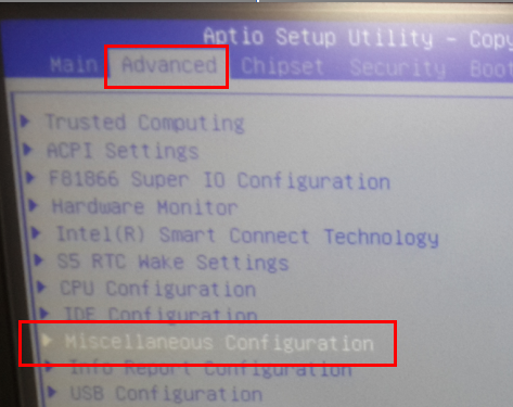
proimages/FAQ/How_to_install_Debain_8.1_on_WEB-A8A0A8A1.3-1.png proimages/FAQ/How_to_install_Debain_8.1_on_WEB-A8A0A8A1.3-2.png
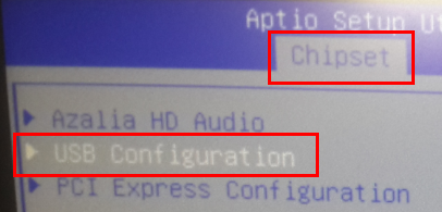
4. Select Chipset > South Bridge > USB Configuration
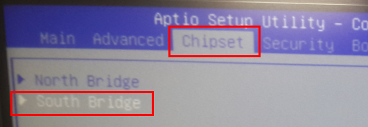
 proimages/FAQ/How_to_install_Debain_8.1_on_WEB-A8A0A8A1.4-1.png proimages/FAQ/How_to_install_Debain_8.1_on_WEB-A8A0A8A1.4-2.png
5. Change XHCI Mode from Smart Auto to Enabled.
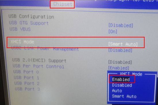
 proimages/FAQ/How_to_install_Debain_8.1_on_WEB-A8A0A8A1.5-1.png

6. Press F10 key to save and exit BIOS setup screen
7. Boot from USB-CD-ROM and follow instruction on screen to setup Debain.
8. When screen request to scan other Disc ,select No.
9. When screen request to set mirror for network ,Select No.
10.Other setting can follow instruction on screen to setup.
11 Done. 
1. Press“Del”key when system power on.  
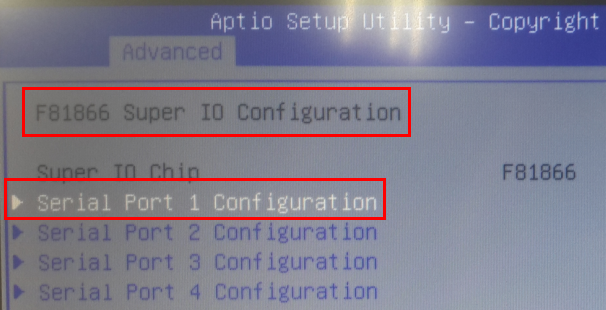
2. Select Advanced > F81866 super IO configuration
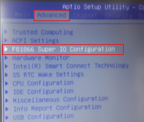
 proimages/FAQ/How_to_change_the_function_mode_of_COM_1.1.png

3. Select Serial port 1.
 proimages/FAQ/How_to_change_the_function_mode_of_COM_1.2.png

4. Select the Function item to check change mode.
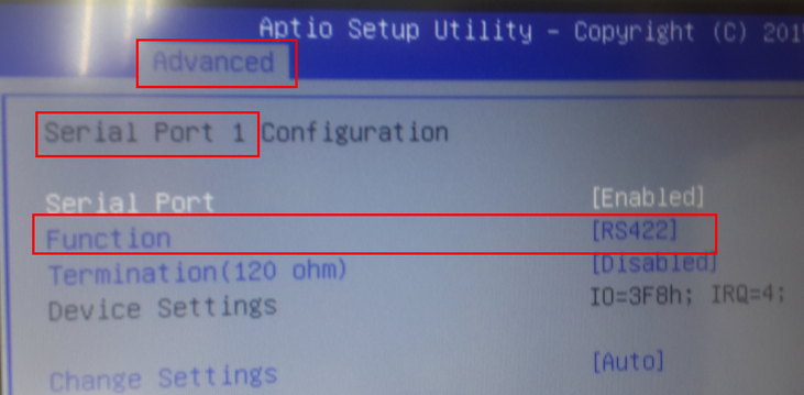
proimages/FAQ/How_to_change_the_function_mode_of_COM_1.3.png
1.Please help to remove all screws on Heaksink and remove Heatsink
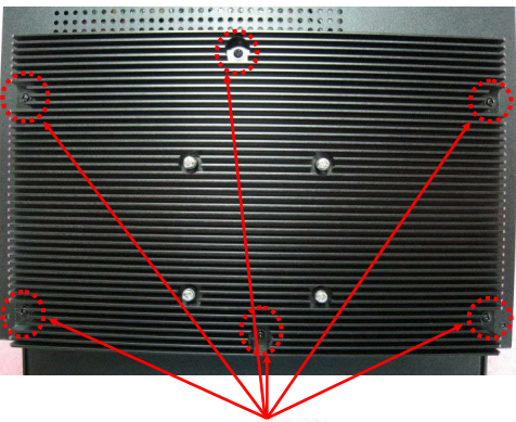
 proimages/FAQ/How_to_check_display_cable_WLP7A20.1.png

2. Please remove all screws at below location:
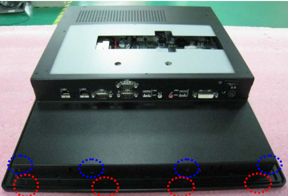
 proimages/FAQ/How_to_check_display_cable_WLP7A20.2-1.pngproimages/FAQ/How_to_check_display_cable_WLP7A20.2-2.png


3.Disconnect Power button cable , DC in cable and remove rear cover.
proimages/FAQ/How_to_swap_the_touch_controller_-_WLP-7A20.3.jpg

4.Pull open the connectors of flexible cable.
proimages/FAQ/How_to_swap_the_touch_controller_-_WLP-7A20.4.jpg

5.Pull out the flexible cables and remove the power connector and 4 screws.
proimages/FAQ/How_to_swap_the_touch_controller_-_WLP-7A20.5-1.jpg proimages/FAQ/How_to_swap_the_touch_controller_-_WLP-7A20.5-2.jpg

6.Check the mode name of touch controller.
proimages/FAQ/How_to_swap_the_touch_controller_-_WLP-7A20.6.jpg
Please press del into bios setup screen ,when system boot up 
1.Select  Advanced > Serial Port 1~4 Configuration  
 proimages/FAQ/How_To_Set_RS-485_auto_Flow_In_Bios-Web-8899(A).1.png

2.Serial Port 1 Configuration  
proimages/FAQ/How_To_Set_RS-485_auto_Flow_In_Bios-Web-8899(A).2.png

3.Select RS485 Auto flow and Enable this item.
 proimages/FAQ/How_To_Set_RS-485_auto_Flow_In_Bios-Web-8899(A).3.png

4. Press F10 to save setting
1.Please help to remove all screws on Heaksink and remove Heatsink
 proimages/FAQ/How_to_check_display_cable_WLP7A20.1.png

2. Please remove all screws at below location:
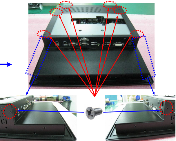
 proimages/FAQ/How_to_check_display_cable_WLP7A20.2-1.pngproimages/FAQ/How_to_check_display_cable_WLP7A20.2-2.png

3.Disconnect DC in cable and remove rear cover & Power button cable .
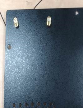
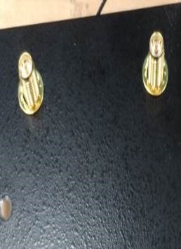
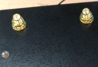
4.Remove the cap on rear cover then install antenna/washer/Nuts to rear cover .
 proimages/FAQ/How_To_Install_Wireless_LAN-WLP-7A20.4-1.jpgproimages/FAQ/How_To_Install_Wireless_LAN-WLP-7A20.4-2.jpgproimages/FAQ/How_To_Install_Wireless_LAN-WLP-7A20.4-3.jpgproimages/FAQ/How_To_Install_Wireless_LAN-WLP-7A20.4-4.jpg

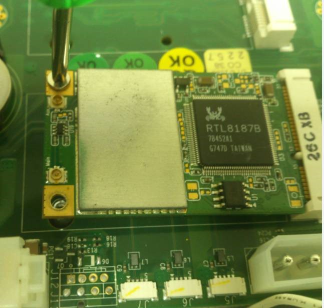
5.install mini PCIe Wifi card by two screws.
 proimages/FAQ/How_To_Install_Wireless_LAN-WLP-7A20.5.jpg

6.Connect antenna cable to Main  & AUX connector .
proimages/FAQ/How_To_Install_Wireless_LAN-WLP-7A20.6.jpg
proimages/FAQ/How_To_Install_Wireless_LAN-WLP-7A20.6-2.jpg

7.Add type to fix antenna
proimages/FAQ/How_To_Install_Wireless_LAN-WLP-7A20.7.jpg

For Half card Kit (With bracket) pre-assembly :
proimages/FAQ/How_To_Install_Wireless_LAN-WLP-7A20.7-2.jpgproimages/FAQ/How_To_Install_Wireless_LAN-WLP-7A20.7-3.jpg
proimages/FAQ/How_To_Install_Wireless_LAN-WLP-7A20.7-3.jpg

For Half card Kit (Without bracket).
 proimages/FAQ/How_To_Install_Wireless_LAN-WLP-7A20.7-5.jpgproimages/FAQ/How_To_Install_Wireless_LAN-WLP-7A20.7-6.jpgproimages/FAQ/How_To_Install_Wireless_LAN-WLP-7A20.7-7.jpg
1.Please help to remove all screws on Heaksink and remove Heatsink
 proimages/FAQ/How_to_check_display_cable_WLP7A20.1.png

2. Please remove all screws at below location:
 proimages/FAQ/How_to_check_display_cable_WLP7A20.2-1.pngproimages/FAQ/How_to_check_display_cable_WLP7A20.2-2.png

 
Please press del into bios setup screen ,when system boot up 
1.Please help to remove all screws on Heaksink and remove Heatsink
 proimages/FAQ/How_to_check_display_cable_WLP7A20.1.png

2. Please remove all screws at below location:
 proimages/FAQ/How_to_check_display_cable_WLP7A20.2-1.pngproimages/FAQ/How_to_check_display_cable_WLP7A20.2-2.png

3.Disconnect Power button cable ,DC in cable and remove rear cover.
4.Remove coin battery and short battery as below :
 proimages/FAQ/How_To_clear_CMOS-WLP-7A20.pngproimages/FAQ/How_To_clear_CMOS-WLP-7A20.2.png

5.Re-install battery /rear cover /heatsink back and power on system to check Failure symptom again.
 
6. Done
Step1.
Boot up system and press “Del” go enter BIOS menu.
Choose “Chipset”>“System Agent (SA) Configuartion”.
 proimages/FAQ/How_to_check_VRAM_of_WLP7A20.1.jpg
Step2.
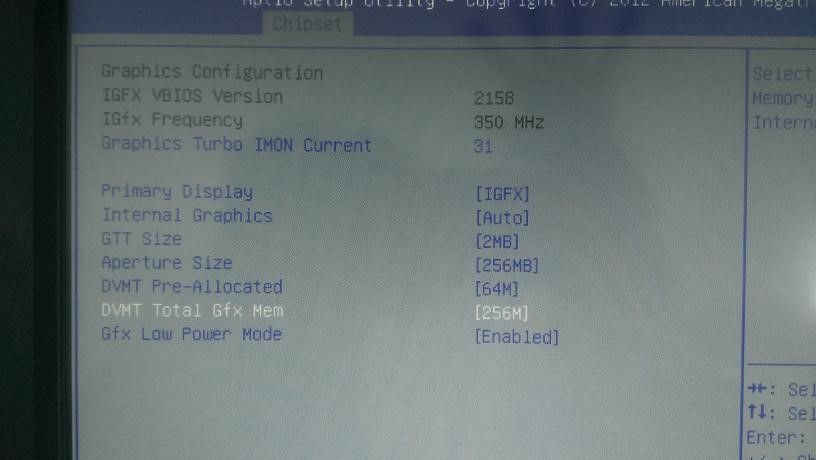
Choose “Graphics Configuration”
 proimages/FAQ/How_to_check_VRAM_of_WLP-7A20.2.jpg
Step3.
Choose “DVMT Total Gfx Mem”.
Default setting is 256MB.
 proimages/FAQ/How_to_check_VRAM_of_WLP-7A20.3.jpg
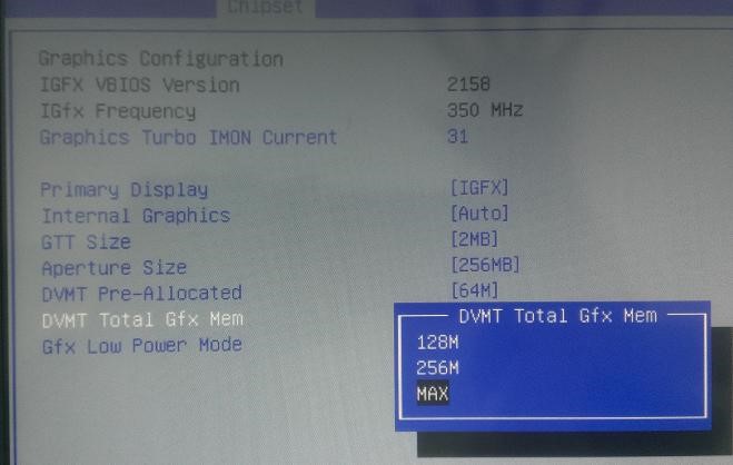
Step4.
The item of “DVMT Total Gfx Mem” can set 128M,256M and MAX.
 proimages/FAQ/How_to_check_VRAM_of_WLP-7A20.4.jpg
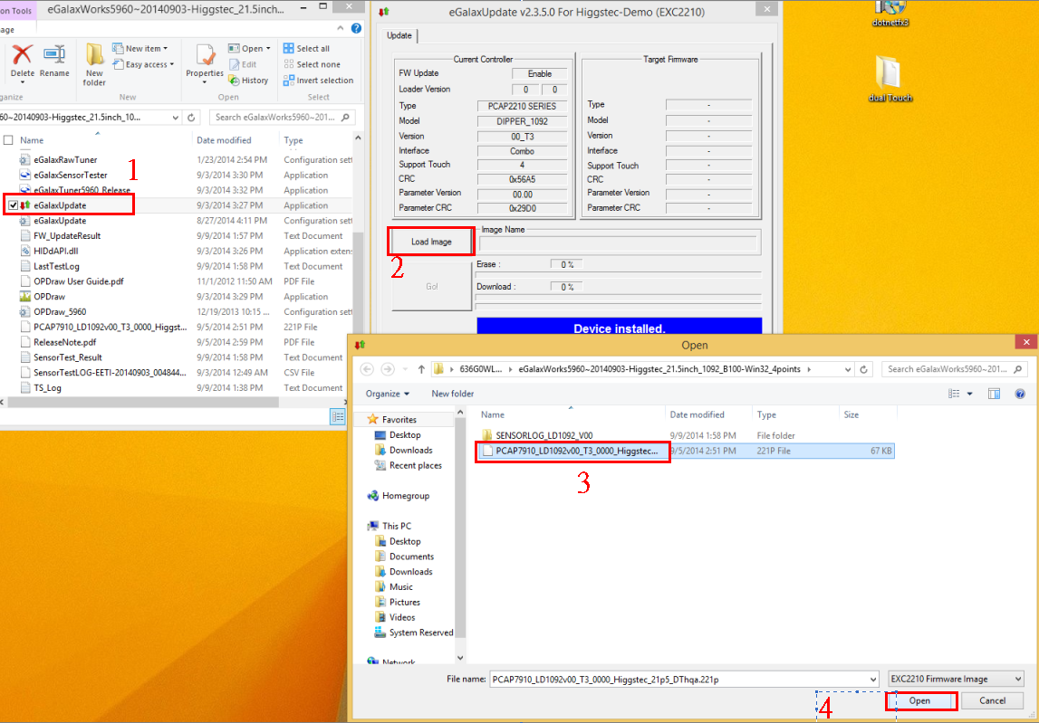
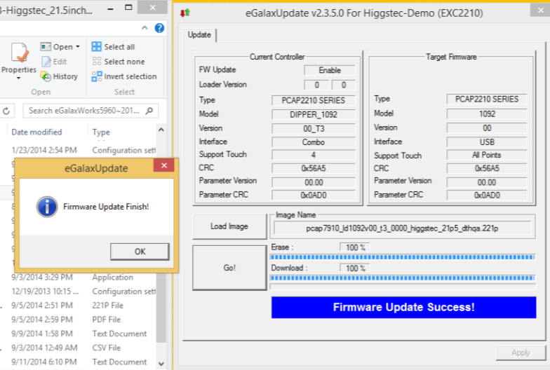
1.Run eGalaxUpdate.exe > Load image > Select image > OPEN. 
 proimages/FAQ/How_to_check_touch_FW.1.png
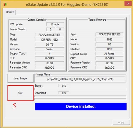
2. Press “Go” to re-flash FW.
 proimages/FAQ/How_to_check_touch_FW.2.jpg

3. Update finished message. 
 proimages/FAQ/How_to_check_touch_FW.3.png
4. Close program and check function.
Please press del into bios setup screen ,when system boot up 
1.Please help to remove all screws on Heaksink and remove Heatsink
 proimages/FAQ/How_to_check_display_cable_WLP7A20.1.png

2. Please remove all screws at below location:
 proimages/FAQ/How_to_check_display_cable_WLP7A20.2-1.pngproimages/FAQ/How_to_check_display_cable_WLP7A20.2-2.png

3.Disconnect Power button cable ,DC in cable and remove rear cover.
4. Check LVDS cable status and connection:
 proimages/FAQ/How_to_check_display_cable_WLP7A20.4-1.pngproimages/FAQ/How_to_check_display_cable_WLP7A20.4-2.png

5. Re-install rear cover /heatsink back and power on system to check Failure symptom again.
6. Done
Please press del into bios setup screen ,when system boot up 
1.Please help to remove all screws on Heaksink and remove Heatsink
 proimages/FAQ/How_to_check_display_cable_WLP7A20.1.png

2. Please remove all screws at below location:
 proimages/FAQ/How_to_check_display_cable_WLP7A20.2-1.pngproimages/FAQ/How_to_check_display_cable_WLP7A20.2-2.png

3.Disconnect Power button cable ,DC in cable and remove rear cover.
4. Check LVDS cable status and connection:
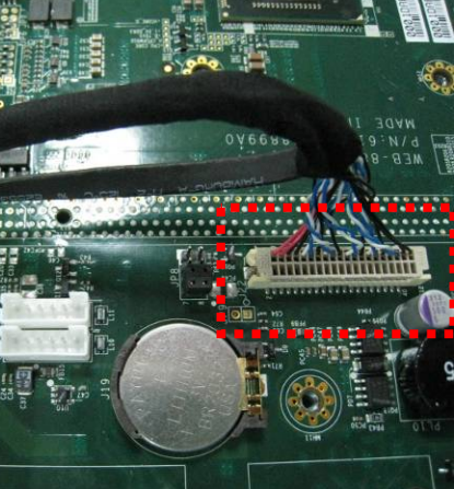
 proimages/FAQ/How_to_check_display_cable_WLP7A20.4-1.pngproimages/FAQ/How_to_check_display_cable_WLP7A20.4-2.png

5. Check inverter cable status and connection:
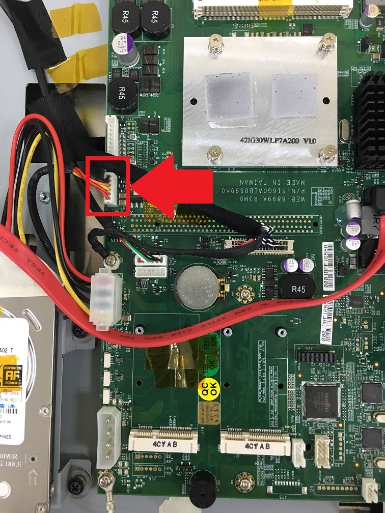
 proimages/FAQ/How_to_check_display_cable_WLP7A20.5.jpg

6. Re-install rear cover /heatsink back and power on system to check Failure symptom again.
7. Done

1.     Remove all screws on back housing.(Remove power adapter first)
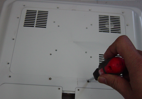
proimages/FAQ/how_to_clear_cmos_1.png

2.     Open I/O cover and remove two screws
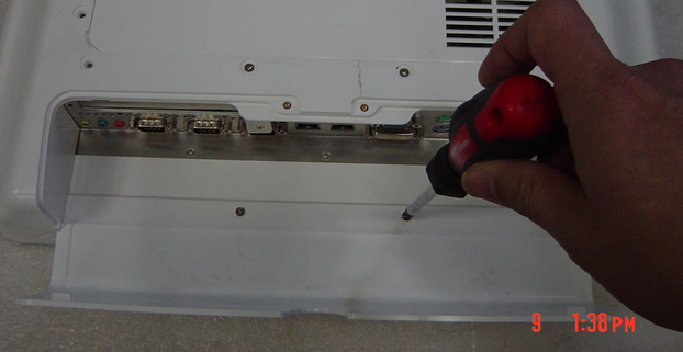


proimages/FAQ/how_to_clear_cmos_2.png

3.     Remove back housing

proimages/FAQ/how_to_clear_cmos_3.png

4.     Remove all screw on rear cover

proimages/FAQ/how_to_clear_cmos_4.png

5.     Open the Rear cover and remove Fan from connector .
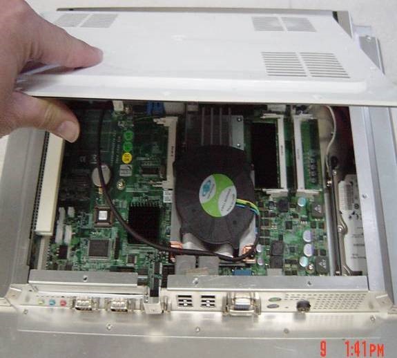
proimages/FAQ/how_to_clear_cmos_5.png.jpgproimages/FAQ/how_to_clear_cmos_5-2.png.jpg

6.Remove battery from battery socket and short two pins:
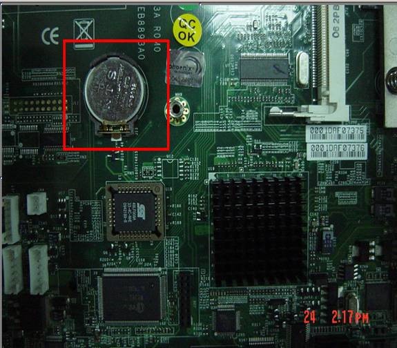
proimages/FAQ/how_to_clear_cmos_6-1.jpgproimages/FAQ/how_to_clear_cmos_6.jpg

7.Re-install battery back and power on system to check Failure symptom again.

8. Done

e-News Subscribe

e-News Subscribe