Quick One Key OS Recovery
The procedure to OS Recovery Function:
-
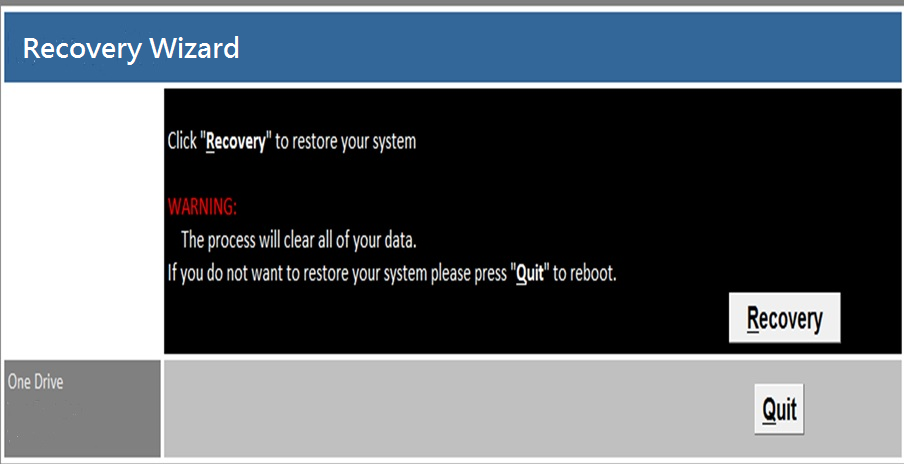
Turn on the power to start the computer, and then press “F6” to enable recovery wizard, as the below shown screen shot. Click ”Recovery” icon to proceed operating system recovery, back to the original setting while shipping out from the factory.
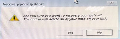
- A warning message to remind the data loss risk will show up and please make sure the data is backed up before recovery and then click “Yes”
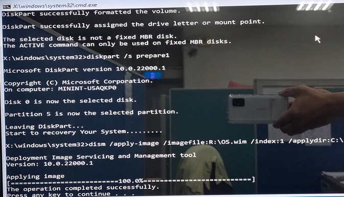
- When the screen indicates “The operation completed successfully”, the OS recovery procedure is successfully completed. The system will automatically restart after OS recovery procedure completed.


| Module | Resistive touch screen | PCT |
| WLP-10 WTP-10 |
05 | 05 |
| WLP-12 | 05 | 05 |
| WLP-15 WTP-15 |
05 | 05 |
| WLP-16 | 05 | 05 |
| WLP-17 | 05 | 05 |
| WLP-19 WTP-19 |
05 | 05 |
| WLP-22 WTP-22 |
05 | 05 |
| WTP-24 | 05 |
Bettery Mode : Yellow
Bettery Low : Yellow blinking

Battery Charging/Discharging conditions of WEB-8899

How to disable Battery before system shipment.
- Shutdown system.
- Remove AC power cord, then the battery LED will on.
- Press volume up key 10 seconds, then all LED will turn on and turn off

- Battery function already disable.
Remark: Plug in AC power cord, Press power button then battery function will auto enable.

Battery function
-
Capacity check: You can check Battery by Windows power option – Same as laptop.

- Low Battery: In low battery mode ,System will go into S4 stage -Same as laptop. (Percentage will base on OS setting).
- Estimate discharge time table, Unit: Minutes.

| Items |
WMP-176(88.8W)
|
WMP-196(89.3W)
|
WMP-226(79.3W) |
| Discharge time | 14.2 |
14.4 |
18.5 |
| Items |
WMP-177(70.8W)
|
WMP-197(71.3W)
|
WMP-227(61.3W)
|
| Discharge time | 21.5 | 21 | 24 |
| Intel VGA setting | WMP-226 Panel | WMP-226-DVI output | Support or not |
| Clone mode | 1366*768 | 1366*768 | Yes |
| 1920*1080 | 1920*1080 | Yes | |
| 1920*1080 | 1366*768 | NO | |
| Extend Mode | 1920*1080 | 1366*768 | Yes |
| 1366*768 | 1366*768 | Yes | |
| 1920*1080 | 1920*1080 | Yes |
The speakers optimize default of WMP-248(9) is:
- Both left and right are 100 at the item “Balance” of “realtek HD audio output”
The microphone optimize default of WMP-248(9) is: - The item “Listen to this device” of “Listen” tab is uncheck.
- The item “Microphone Boost” of “Levels” tab is +20dB.
If the setting is different from optimize default, please follow the step as below:
Step 1.
Right click the sound icon and choose “Playback devices”.
Step2.
Choose “Playback” tab and click “Properties” of the Speakers.
Choose “Levels” tab and click “Balance”
Set L&R to 100 then click OK.


Step 3.
Choose “Recording” tab and click “Properties” of the Microphone.
Choose “Listen” tab and uncheck “Listen to this device”.
Click OK.
Step 4.
Choose “Recording” tab and click “Properties” of the Microphone.
Choose “Levels” tab and set the “Microphone Boost” to +20.0dB. (the best defaults) Click OK.

Note: If system still has Echo sound, you can change the Microphone Boost level to lower.
BIOS Setup Information
BIOS Introduction
The AMI BIOS (Basic Input / Output System) installed in your computer system’s ROM supports Intel processors. The BIOS provides critical low-level support for a standard device such as disk drives, serial ports and parallel ports. It also adds virus and password protection as well as special support for detailed fine-tuning of the chipset controlling the entire system.
BIOS Setup
The AMI BIOS provides a Setup utility program for specifying the system configurations and settings. The BIOS ROM of the system stores the Setup utility. When you turn on the computer, the AMI BIOS is immediately activated. Pressing the key immediately allows you to enter the Setup utility. If you are a little bit late pressing the key, POST (Power On Self Test) will continue with its test routines, thus preventing you from invoking the Setup. If you still wish to enter Setup, restart the system by pressing the ”Reset” button or simultaneously pressing the and keys. You can also restart by turning the system Off and back On again. The following message will appear on the screen:
Press
In general, you press the arrow keys to highlight items, to select, the and keys to change entries, for help and to quit.
When you enter the Setup utility, the Main Menu screen will appear on the screen. The Main Menu allows you to select from various setup functions and exit choices.
Main
This section provides information on the BIOS information, Memory information, and Battery information
System Date
Set the system date. Use the key to switch between data elements.
System Time
Set the system time. Use the key to switch between time elements.
Advanced

Launch OpROM Support
- Launch PXE OpROM: Enables or disables Boot Option for Legacy Network Devices.
- Launch Storage OpROM: Enables or disables Boot Option for Legacy Mass Storage Devices with Option ROM.
PCI Subsystem Settings
- PCI ROM Priority: In Case of multiple Option ROMs (Legacy and EFI Compatible), specifies what PCI Option ROM to launch.
- PCI Latency Timer: Value to be programmed into PCI Latency Timer Register.
- VGA Palette Snoop: Enables or disables VGA Palette Registers Snooping.
- PERR# Generation: Enables or Disables PCI Device to Generate PERR#.
- SERR# Generation: Enables or Disables PCI Device to Generate SERR#.
- Relaxed Ordering: Enables or Disables PCI Express Device Relaxed Ordering.
- Extended Tag: If ENABLED allows Device to use 8-bit Tag field as a requester.
- No Snoop: Enables or Disables PCI Express Device No Snoop option.
- Maximum Payload: Set Maximum Payload of PCI Express Device or allow System BIOS to select the value
- Maximum Read Request: Set Maximum Read Request Size of PCI Express Device or allow System BIOS to select the value.
- ASPM Support: Set the ASPM Level: Force L0 – Force all links to L0 State : AUTO – BIOS auto configure : DISABLE – Disables ASPM.
- Extended Synch: If ENABLED allows generation of Extended Synchronization patterns.
ACPI Settings
- Enables ACPI Auto Conf: Enables or Disables BIOS ACPI Auto Configuration.
- Enable Hibernation: Enables or Disables System ability to Hibernate (OS/S4 Sleep State). This option may be not effective with some OS.
- ACPI Sleep State: Select the highest ACPI sleep state the system will enter, when the SUSPEND button is pressed.
S5 RTC Wake Settings
- Wake System with Fixed Time: Enables or disables system wake on alarm event. When enabled, the system will wake on the time specified.
- Wake system with Dynamic Time: Enables or disables system wake on alarm event. When enabled, the system will wake on the current time+Increase minute(s).
F71869 Super IO Configuration
- Serial Port 0 Configuration: Set Parameters of Serial Port 0 (COM A).
- Serial Port 1 Configuration: Set Parameters of Serial Port 1 (COM B).
- F71869 H/W Monitor: Monitor hardware status
CPU Configuration
- Hyper-Threading: Enabled for Windows XP and Linux (OS optimized for Hyper-Threading Technology) and Disabled for other OS (OS optimized for Hyper-Threading Technology)
- Core-Multi Processing: Enable or Disable Core-Multi Processing mode.
- Execute Disable Bit: XD can prevent certain classes of malicious buffer overflow attacks when combined with a supporting OS (Windows Server 2003 SP1, Windows XP SP2, SuSE Linux 9.2, RedHat Enterprise 3 Update 3.)
- Limit CPUID Maximum: Disabled for Windows XP.
IDE Configuration
- ATA or IDE Configuration: Select ATA or IDE configuration.
- Configure SATA AS: Select a configuration for SATA controller.
- HDD Acoustic Power Ma: Option to enable or disable HDD Acoustic Power Management.
- DiPM: Option to enable or disable DiPM
Intel IGD / Display Settings
- DVMT Mode Select: Selects DVMT Mode used by Internal Graphics Device.
- DVMT/FIXED Memory: Selects DVMT/FIXED Mode Memory size used by Internal Graphics Device.
- IGD – Boot Type: Select the Video Device which will be activated during POST. This has no effect if external graphics present.
- LCD Panel Type: Select LCD panel used by Internal Graphics Device by selecting the appropriate setup item.
- Panel Scaling: Select the LCD panel scaling option used by the Internal Graphics Device.
- GMCH BLC Control: Back Light Control Setting
- BIA Control
- Spread Spectrum clock: >>Hardware: Spread is controlled by chip; >>Software: Spread is controlled by BIOS.
- TV1 Standard / TV2 Standard
- Active LFP: Select the Active LFP Configuration. No LVDS:VBIOS does not enable LVDS. INT-LVDS:VBIOS enables LVDS driver by Integrated encoder. SDV0 LVDS:VBIOS enables LVDS driver by SDV0.
USB Configuration
- Legacy USB Support: Allows USB devices to be used in MS-DOS.
- EHCI Hand-off: This is a workaround for 0Ses without EHCI hand-off support. The EHCI ownership change should be claimed by EHCI driver.
- USB transfer time-out: The time-out value for Control, Bulk, and Interrupt transfers.
- Device reset time-out: USB mass storage device Start Unit command time-out.
- Device power-up delay: Maximum time the device will take before it properly reports itself to the HOST Controller. ‘Auto’ uses default value: for a Root port it is 100 ms, for a Hub port the delay is taken from Hub descriptor.
Second Super IO Configuration
- Serial Port 1 Configuration: Set Parameters of Serial Port 1 (COM C).
- Serial Port 2 Configuration: Set Parameters of Serial Port 2 (COM D).
- Serial Port 3 Configuration: Set Parameters of Serial Port 3 (COM E).
- Serial Port 4 Configuration: Set Parameters of Serial Port 4 (COM F).
- Serial Port Console Redirection: Serial Port Console Redirection.
Chipset

Host Bridge/South Bridge
This screen provides information on Host Bridge/South Bridge parameters.
Boot

- Setup Prompt Timeout: Number of seconds to wait for setup activation key. 65535(0xFFFF) means indefinite waiting.
- Bootup Numlock State: Selects the keyboard NumLock state.
- Quiet Boot: Allows you to determine whether to display the AMI Logo at system startup. Disabled displays normal POST message.
- Fast Boot: Enables or disables the quick boot function to speed up the system boot-up process to shorten the waiting time for entering the operating system and to deliver greater efficiency for daily use.
- GateA20 Active: This option is useful when any RT code is executed above 1MB. Upon Request GA20 can be disabled using BIOS services. (Default). Always Do not allow disabling GA20.
- Option ROM Messages: Sets display made for option ROM.
- Interrupt 19 Capture: Enables or disables Option ROMs to Trap Int 19.
- Boot Option Priorities: Specifies the sequence of loading the operating system from the installed hard drives.
Security

Enables or disables the security chip. It is recommended that you use this function with the Administrator/User password.
Save & Exit

Save Options
- Save Changes and Exit: Exit system setup after saving the changes.
- Save Changes and Reset: Reset the system after saving the changes.
- Save Changes: Save the changes done so far to any of setup options.
- Save as User Defaults: Save the changes done so far as User Defaults.
Discard / Restore Options
- Discard Changes and Exit: Exit system setup without saving any changes.
- Discard Changes and Reset: Reset system setup without saving the changes.
- Discard Changes: Discard the changes done so far to any of setup options.
- Restore Defaults: Restore/load default values for all the setup options.
- Restore User Defaults: Restore the User Defaults to all the setup options.
- EFIGUI_FLASH: Press to execute the simple EFI GUI Flash Program
Jumper Setting
JP1 – Backlight Type Selection

| Description | Jumper Setting |
|---|---|
| Analog Inverter | 1-2 |
| PWM Inverter | 2-3(default) |
JP2 – Backlight control level Selection

| Description | Jumper Setting |
|---|---|
| +3.3V | 1-2(default) |
| +5V | OPEN |
JP3 – Touch Panel Type Selection

| Description | Jumper Setting |
|---|---|
| 3M type | 1-2, 3-4 (default) |
| ELO type | 5-6, 7-8 |
JP 4– LVDS Power Selection

| Description | Jumper Setting |
|---|---|
| +3.3VS(for 10”/12”/15”) | 5-6, 7-8 (default) |
| +5VS(for 15.6/17”/19”/21.5) | 1-2, 3-4 |
JP5 – Panel Resolution Selection

JP6 – CMOS Clear

| Description | Jumper Setting |
|---|---|
| Normal Open | 1-2 (default) |
| CMOS Clear | 2-3 |
Connector Definition
PJ1 /PJ2 – HDD Power Connector

| Pin # | Signal Description |
|---|---|
| 1 | +12VS |
| 2 | GND |
| 3 | GND |
| 4 | +5VS |
PJ3 – Power Input Connector


| Pin # | Signal Description |
|---|---|
| 1 | GND |
| 2 | GND |
| 3 | DC In |
| 4 | DC In |
J1 – LCD Inverter Connector

| Pin # | Signal Description |
|---|---|
| 1 | +12VS |
| 2 | +12VS |
| 3 | Backlight Control |
| 4 | Backlight Enable |
| 5 | GND |
| 6 | GND |
J2 – Internal USB 2.0 Connector

| Pin # | Signal Description |
|---|---|
| 1 | +5VSB |
| 2 | +5VSB |
| 3 | Data - |
| 4 | Data + |
| 5 | GND |
| 6 | GND |
J4 – LVDS Connector

| Pin # | Signal Description | Pin # | Signal Description |
|---|---|---|---|
| 39 | GND | 40 | GND |
| 37 | Ground | 38 | GND |
| 35 | A_TXD3+ | 36 | B_TXD3+ |
| 33 | A_TXD3- | 34 | B_TXD3- |
| 31 | GND | 32 | GND |
| 29 | A_CLK+ | 30 | B_CLK+ |
| 27 | A_CLK- | 28 | B_CLK- |
| 25 | GND | 26 | GND |
| 23 | A_TXD2+ | 24 | B_TXD2+ |
| 21 | A_TXD2- | 22 | B_TXD2- |
| 19 | GND | 20 | GND |
| 17 | A_TXD1+ | 18 | B_TXD1+ |
| 15 | A_TXD1- | 16 | B_TXD1- |
| 13 | GND | 14 | GND |
| 11 | A_TXD0+ | 12 | B_TXD0+ |
| 9 | A_TXD0- | 10 | B_TXD0- |
| 7 | GND | 8 | GND |
| 5 | GND | 6 | GND |
| 3 | +LVDS PWR | 4 | +LVDS PWR |
| 1 | +LVDS PWR | 2 | +LVDS PWR |
J5 – Resistance Touch Screen Connector

| Pin # | Signal Description | ||
|---|---|---|---|
| 8-wire | 4-wire | 5-wire | |
| 1 | UL(X+) | UL(X+) | UL(X+) |
| 2 | UR(Y+) | UR(Y+) | UR(Y+) |
| 3 | N/A | N/A | PROBE |
| 4 | LR(X-) | LR(X-) | LR(X-) |
| 5 | LL(Y-) | LL(Y-) | LL(Y-) |
| 6 | X+_DRIVE | N/A | N/A |
| 7 | Y+_DRIVE | N/A | N/A |
| 8 | X-_DRIVE | N/A | N/A |
| 9 | Y-_DRIVE | N/A | N/A |
J6 – For 8051 JTAG

| Pin # | Signal Description | Pin # | Signal Description |
|---|---|---|---|
| 10 | Reserved | 9 | GND |
| 8 | Reserved | 7 | +3.3V |
| 6 | Reserved | 5 | +3.3V |
| 4 | C2D | 3 | GND |
| 2 | GND | 1 | +3.3V |
J7 – Mini PCI Express Socket

J8 – P-CAP Touch Screen Connector *

| Pin # | Signal Description |
|---|---|
| 1 | +5VSB |
| 2 | +5VSB |
| 3 | Data - |
| 4 | Data + |
| 5 | Ground |
| 6 | Ground |
* Res(J10) with P-CAP(J14) select one
J9 – TPM / ID-394

| Pin # | Signal Description | Pin # | Signal Description |
|---|---|---|---|
| 16 | +3.3VSB | 15 | SUS_STAT# |
| 14 | SMB DATA | 13 | GND |
| 12 | SMB CLK | 11 | Debug CLK |
| 10 | CLKRUN# | 9 | LPC Frame# |
| 8 | +5VSB | 7 | LPC AD3 |
| 6 | +3.3VS | 5 | LPC AD2 |
| 4 | SERIRQ | 3 | LPC AD1 |
| 2 | PLT reset# | 1 | LPC AD0 |
J10 – CFast Card Interface

| Pin # | Pin # | Signal Description | Signal Description |
|---|---|---|---|
| S1 | SGND | S2 | A+ |
| S3 | A- | S4 | SGND |
| S5 | B- | S6 | B+ |
| S7 | SGND | P1 | CDI |
| P2 | GND | P3 | TBD |
| P4 | TBD | P5 | TBD |
| P6 | TBD | P7 | GND |
| P8 | LED1 | P9 | LED2 |
| P10 | TBD | P11 | TBD |
| P12 | IFDET | P13 | PWR |
| P14 | PWR | P15 | PGND |
| P16 | PGND | P17 | CDO |
J12 – BIOS Socket

J13 – Battery Socket

| Pin # | Signal Description |
|---|---|
| 1 |
RTC +3.3V
|
| 2 |
GND
|
J14 – Standard SATA Interface

| Pin # | Signal Description |
|---|---|
| 1 |
Ground
|
| 2 | Tx+ |
| 3 | Tx- |
| 4 |
Ground
|
| 5 | Rx- |
| 6 | Rx+ |
| 7 | Ground / +5VS |
J15 – PS2 KB/MS Connector

| Pin # | Signal Description |
|---|---|
| 1 | KBDATA |
| 2 | MSDATA |
|
3
|
Ground
|
| 4 | +5VSB |
| 5 | KBCLK |
| 6 | MSCLK |
J16 – Front Panel Connector

| Pin # | Signal Description |
|---|---|
| 4 | PWR_LED# |
| 3 | +3.3VSB |
| 2 | +3.3VSB |
| 1 | SATA_LED# |
J17 – Internal COM4 Serial Port

| Pin # | Signal Description | Pin # | Signal Description |
|---|---|---|---|
| 2 | 232_DSR# | 1 | 232_DCD# |
| 4 | 232_RTS# | 3 | 232_SIN |
| 6 | 232_CTS# | 5 | 232_SOUT |
| 8 | 232_RI# | 7 | 232_DTR# |
| 10 | +5VS | 9 | GND |
J18 – Internal COM3 Serial Port

| Pin # | Signal Description | Pin # | Signal Description |
|---|---|---|---|
| 2 | 232_DSR# | 1 | 232_DCD# |
| 4 | 232_RTS# | 3 | 232_SIN |
| 6 | 232_CTS# | 5 | 232_SOUT |
| 8 | 232_RI# | 7 | 232_DTR# |
| 10 | +5VS | 9 | GND |
J19, J20 – RIGHT / LEFT CH for Speaker

| Pin # | Signal Description | |
|---|---|---|
| J34 (RIGHT CH) | J38 (LEFT CH) | |
| 1 | ROUT+ | LOUT+ |
| 2 | ROUT- | LOUT- |
J21 – Power Switch Connector

| Pin # | Signal Description |
|---|---|
| 1 | PowerON |
| 2 | GND |
J22 – Internal COM1 Serial Port

| Pin # | Signal Description | Pin # | Signal Description |
|---|---|---|---|
| 2 | 232_DSR# | 1 | 232_DCD# |
| 4 | 232_RTS# | 3 | 232_SIN |
| 6 | 232_CTS# | 5 | 232_SOUT |
| 8 | 232_RI# | 7 | 232_DTR# |
| 10 | +5VS | 9 | GND |
J23 – Internal COM2 Serial Port

| Pin # | Signal Description | Pin # | Signal Description |
|---|---|---|---|
| 2 | 232_DSR# | 1 | 232_DCD# |
| 4 | 232_RTS# | 3 | 232_SIN |
| 6 | 232_CTS# | 5 | 232_SOUT |
| 8 | 232_RI# | 7 | 232_DTR# |
| 10 | +5VS | 9 | GND |
J24 / J25 –External RJ45 Ethernet Port

Activity / Link LED
| Status | Description |
|---|---|
| OFF | No Link |
| Blinking | Data Activity |
| ON | Link |
| Status | Description |
|---|---|
| OFF | 10 Mbps |
| Green | 100 Mbps |
| Orange | 1 Gbps |
J26,J27,J28 – External USB 2.0 Port

| Pin # | Signal Description |
|---|---|
| 1 | +5V |
| 2 | USB_D- |
| 3 | USB_D+ |
| 4 | GND |
J29 – External USB 3.0 Port

| Pin # | Signal Description |
|---|---|
| 1 | +5V |
| 2 | USB_D- |
| 3 | USB_D+ |
| 4 | GND |
| 5 | SSRX1- |

How To boot from USB flash disk
-
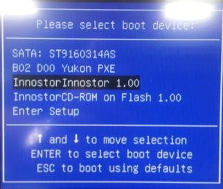
Press F11 when system boot and select USB stick .
- If still can’t boot from USB stick:

2.1 press DEL key into BIOS setup screen.
2.2 Advanced 🡪 USB configuration🡪 Change USB stick setting from Auto to Hard Disk.
2.3 Press F10 🡪 Reboot system 🡪 Press F11 🡪 Select USB stick.--> boot from USB stick.

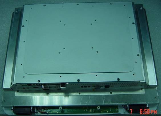
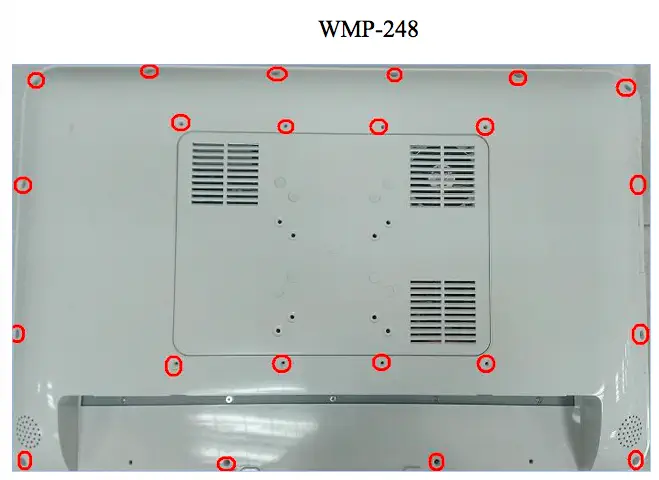
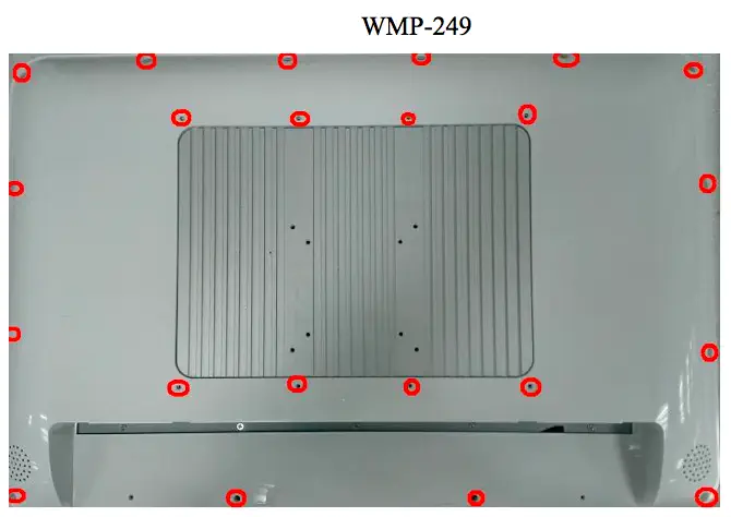
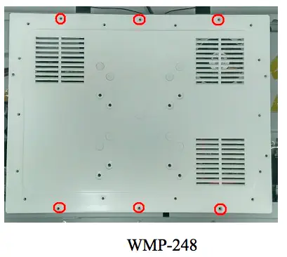
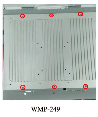
- Remove all screws on back housing.
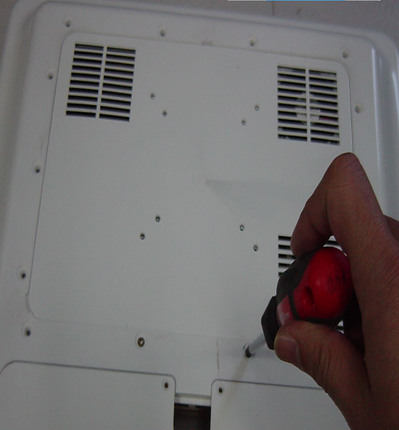
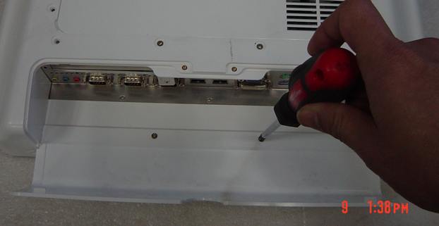
- Open I/O cover and remove two screws
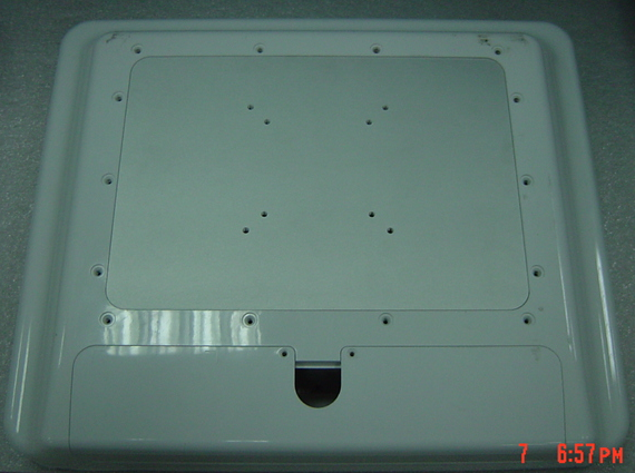
- Remove back housing
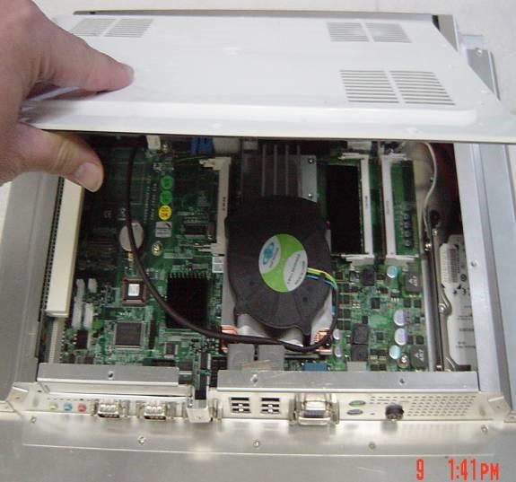
- Remove all screw on rear cover
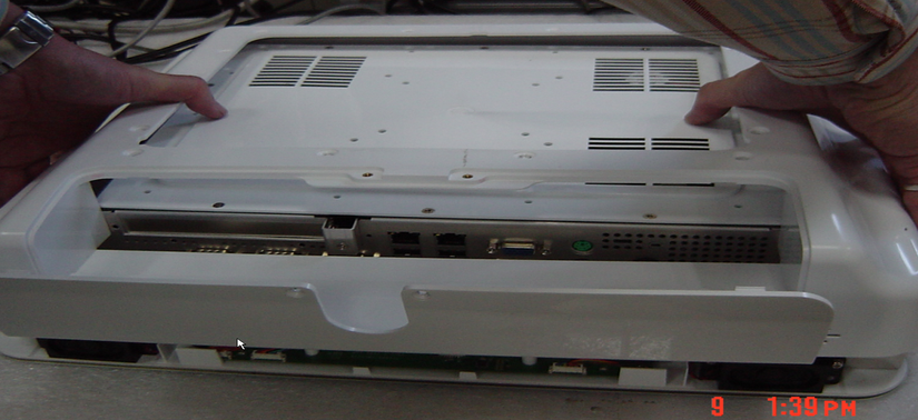
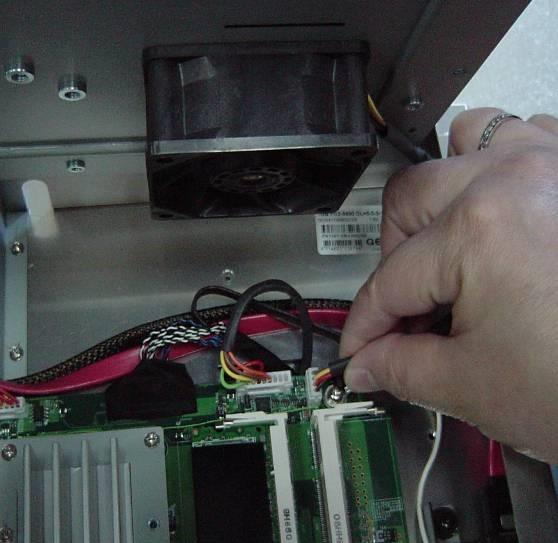
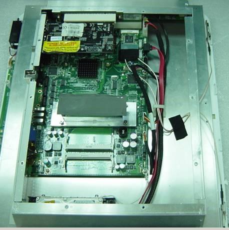
- Open the Rear cover and remove Fan from connector.
- Install antenna as below: 191
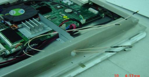
192/195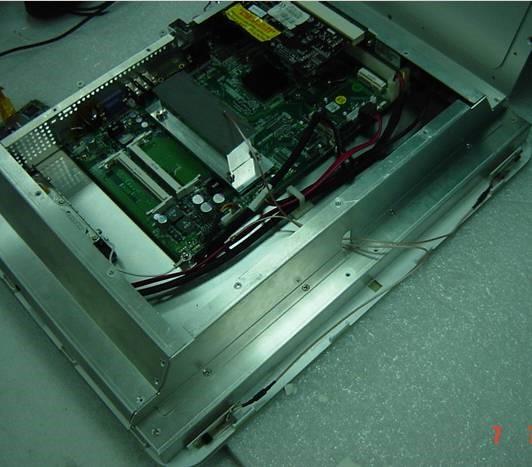
- Fix antenna in front bezel.
- Mini-PCI card fix antenna as below (191/192 only):
- Fix Mini PCIe Lan card by two screws as below:
- Mini-PCIe Lan card antenna fix as below:


- Remove all screws on rear housing
.
Remove back housing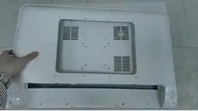
-
Remove all screw on rear cover
-
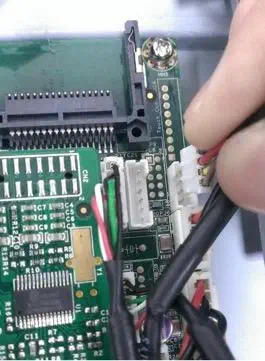
Open the Rear cover and remove Fan from connector .(WMP-248 ONLY)
-
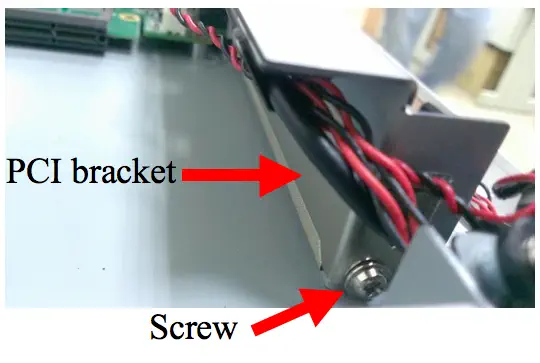
Remove Screw and PCI bracket.
-
Install PCI-E card
-
Fix PCI-E card by screw
- Install the rear cover and back housing.
-
Done.


1.Remove all Rubber plug and screws on rear housing.

2.Remove the HDD cover and rear housing.

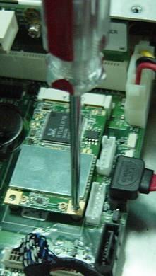
3.Remove all the screws on the bracket, then open the bracket.

4.Short the two pins of the coin battery, and set the JP5 to 2-3(default is 1-2).

5.Set the JP5 to 1-2, and install the coin battery, bracket, the rear housing, and the HDD cover.
1. Remove all Rubber plug and screws on rear housing.

2.
Remove HDD cover & rear cover


3.Remove PCI bracket and install card.


4.Done.
1.
Release screws on rear cover as below:


2. Remove rear cover and disconnect power switch cable.

3.
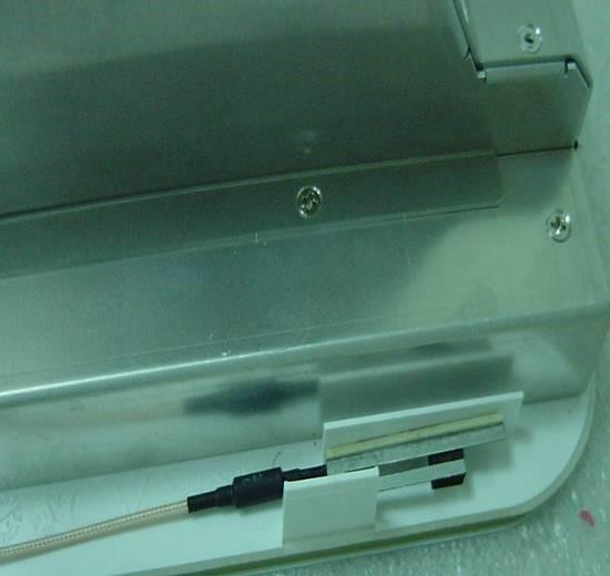
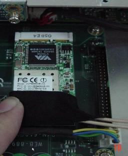
Check the cable connection of touch, and check whether there has any damage on the cable.


4.Done.
1. Release screws on rear cover as below:


2. Remove rear cover and disconnect power switch cable.

3.
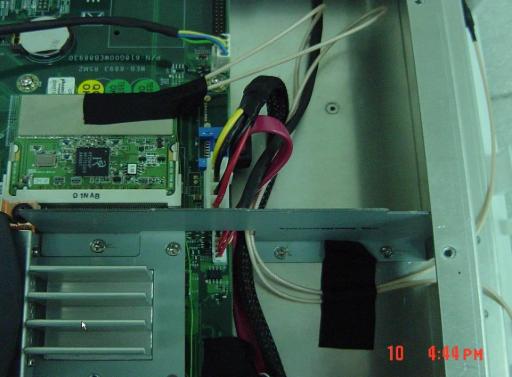
Check cable connection of SATA and power

4.Done.
1. When system power on(Connect USB CD-ROM) , press del key into BIOS setup screen .
2.
Select Advanced > USB configuration > Change CD-ROM setting from AUTO to CD-ROM


3. Select Advanced > Miscellaneous Config… > Show/Hide hidden items > Enable


4. Select Chipset > South Bridge > USB Configuration


5. Change XHCI Mode from Smart Auto to Enabled.

6. Press F10 key to save and exit BIOS setup screen
7. Boot from USB-CD-ROM and follow instruction on screen to setup Debain.
8. When screen request to scan other Disc ,select No.
9. When screen request to set mirror for network ,Select No.
10.Other setting can follow instruction on screen to setup.
11 Done.
1. Press “ Del ” key when system power on.
2.
Select Advanced > F81866 super IO configuration

3. Select Serial port 1.

4. Select the Function item to check change mode.

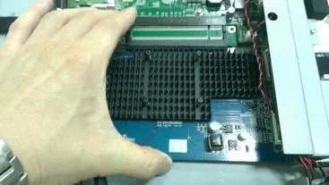
1. Please help to remove all screws on Heaksink and remove Heatsink

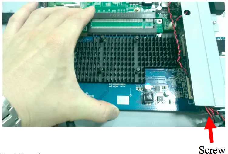
2. Please remove all screws at below location:


3. Disconnect Power button cable , DC in cable and remove rear cover.

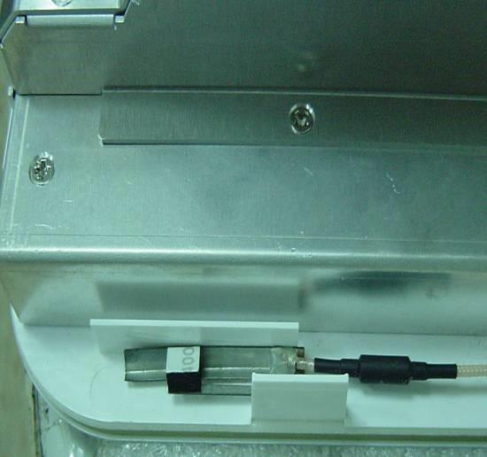
4. Pull open the connectors of flexible cable.

4. Pull out the flexible cables and remove the power connector and 4 screws.


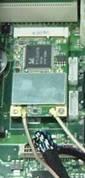
6. Check the mode name of touch controller.

Please press del into bios setup screen ,when system boot up
1. Select Advanced > Serial Port 1~4 Configuration

2. Serial Port 1 Configuration

3. Select RS485 Auto flow and Enable this item.

4. Press F10 to save setting
1. Please help to remove all screws on Heaksink and remove Heatsink

2. Please remove all screws at below location


3. Disconnect DC in cable and remove rear cover & Power button cable .
4. Remove the cap on rear cover then install antenna/washer/Nuts to rear cover .


5. install mini PCIe Wifi card by two screws.

6. Connect antenna cable to Main & AUX connector .


7. Add type to fix antenna

For Half card Kit (With bracket) pre-assembly :


For Half card Kit (Without bracket).


1.
Please help to remove all screws on Heaksink and remove Heatsink
2. Please remove all screws at below location
Please press del into bios setup screen ,when system boot up
1. Please help to remove all screws on Heaksink and remove Heatsink

2. Please remove all screws at below location:

3. Disconnect Power button cable ,DC in cable and remove rear cover.
4. Remove coin battery and short battery as below :


5. Re-install battery /rear cover /heatsink back and power on system to check Failure symptom again.
6. Done
1.
Boot up system and press “Del” go enter BIOS menu.
Choose “Chipset”>“System Agent (SA) Configuartion”.

2.
Choose “Graphics Configuration”
3.
Choose “DVMT Total Gfx Mem”.
Default setting is 256MB.
4.
The item of “DVMT Total Gfx Mem” can set 128M,256M and MAX.
1. Run eGalaxUpdate.exe > Load image > Select image > OPEN.

2. Press “Go” to re-flash FW.
3. Update finished message. 
4. Close program and check function.
Please press del into bios setup screen ,when system boot up
1. Please help to remove all screws on Heaksink and remove Heatsink
2. Please remove all screws at below location:
3.Disconnect Power button cable ,DC in cable and remove rear cover.
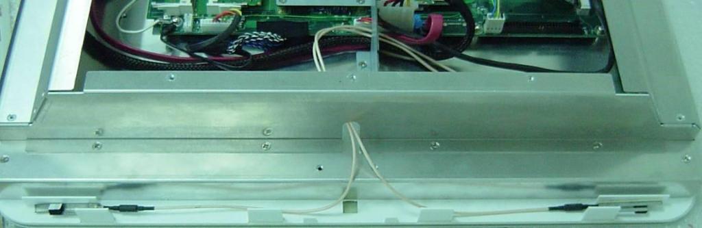
4. Check LVDS cable status and connection:


5. Re-install rear cover /heatsink back and power on system to check Failure symptom again.
6. Done
Please press del into bios setup screen ,when system boot up
1. Please help to remove all screws on Heaksink and remove Heatsink
2. Please remove all screws at below location:
3.Disconnect Power button cable ,DC in cable and remove rear cover.
4. Check LVDS cable status and connection:


5. Check inverter cable status and connection:
6. Re-install rear cover /heatsink back and power on system to check Failure symptom again.
7. Done

1. Remove all screws on back housing.(Remove power adapter first)

2. Open I/O cover and remove two screws

3. Remove back housing
4. Remove all screw on rear cover
5. Open the Rear cover and remove Fan from connector .


6. Remove battery from battery socket and short two pins:


7.Re-install battery back and power on system to check Failure symptom again.
8. Done